
文章目录
前言一、OSPF基础配置拓扑图R1配置R2配置状态、路由查询和PING验证
一、OSPF接口验证1.在R1侧添加接口验证2.查看此时的OSPF状态3.补充R2的接口认证
二、调整Hello报文时间知识点1.在R1侧调整Hello时间2.查看此时的OSPF状态3.补充R2的接口Hello时间
三、配置路由过滤1.在R1侧添加路由过滤2.此时R2查看路由3.从PC3 PING测试验证
四、路由聚合1.在R1侧对引入的直连路由(外部路由)进行聚合2.此时R2查看路由3.从PC3 PING测试验证
总结资料获取
123
前言
在前几期的推文中,我们已经系统介绍了OSPF协议的以下内容:
第一章 【OSPF配置详解(基本功能)】
第二章 【OSPF区域的划分、ABR、路由聚合、LSDB】
第三章 【OSPF STUB 区域】
第四章 【OSPF NSSA与STUB区域对比】
在本期内容中,我们将进一步讲解OSPF配置中的几种常见应用场景,包括
认证配置、Hello报文时间调整、路由过滤与路由聚合
一、OSPF基础配置
拓扑图
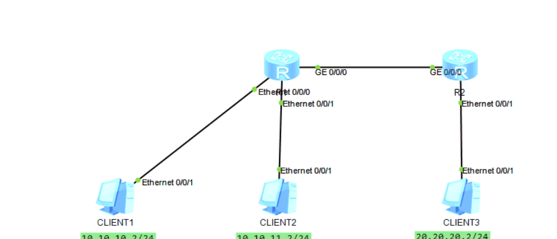
R1配置
interface Ethernet0/0/0
 description To-[PC1]
 ip address 10.10.10.1 255.255.255.0
#
interface Ethernet0/0/1
 description To-[PC2]
 ip address 10.10.11.1 255.255.255.0
#
interface GigabitEthernet0/0/0
 description To-[R1]
 ip address 192.168.10.1 255.255.255.252
#
interface LoopBack0
 ip address 1.1.1.1 255.255.255.255
#
ospf 100 router-id 1.1.1.1
 import-route direct
 area 0.0.0.0
  network 192.168.10.0 0.0.0.3
R2配置
interface Ethernet0/0/1
 description To-[PC3]
 ip address 20.20.20.1 255.255.255.0
#
interface GigabitEthernet0/0/0
 description To-[R1]
 ip address 192.168.10.2 255.255.255.252
#
interface LoopBack0
 ip address 2.2.2.2 255.255.255.255
#
ospf 100 router-id 2.2.2.2
 import-route direct
 area 0.0.0.0
  network 192.168.10.0 0.0.0.3
状态、路由查询和PING验证
# R1
<R1>disp ospf peer brief

	 OSPF Process 100 with Router ID 192.168.10.1
		  Peer Statistic Information
 ----------------------------------------------------------------------------
 Area Id          Interface                        Neighbor id      State
 0.0.0.0          GigabitEthernet0/0/0             2.2.2.2          Full        -- 状态为Full
 ----------------------------------------------------------------------------

<R1>disp ip routing-table
Route Flags: R - relay, D - download to fib
------------------------------------------------------------------------------
Routing Tables: Public
         Destinations : 11       Routes : 11

Destination/Mask    Proto   Pre  Cost      Flags NextHop         Interface

        1.1.1.1/32  Direct  0    0           D   127.0.0.1       LoopBack0
        2.2.2.2/32  O_ASE   150  1           D   192.168.10.2    GigabitEthernet0/0/0
     10.10.10.0/24  Direct  0    0           D   10.10.10.1      Ethernet0/0/0
     10.10.10.1/32  Direct  0    0           D   127.0.0.1       Ethernet0/0/0
     10.10.11.0/24  Direct  0    0           D   10.10.11.1      Ethernet0/0/1
     10.10.11.1/32  Direct  0    0           D   127.0.0.1       Ethernet0/0/1
     20.20.20.0/24  O_ASE   150  1           D   192.168.10.2    GigabitEthernet0/0/0  -- 在R1上可以看到PC3的路由
      127.0.0.0/8   Direct  0    0           D   127.0.0.1       InLoopBack0
      127.0.0.1/32  Direct  0    0           D   127.0.0.1       InLoopBack0
   192.168.10.0/30  Direct  0    0           D   192.168.10.1    GigabitEthernet0/0/0
   192.168.10.1/32  Direct  0    0           D   127.0.0.1       GigabitEthernet0/0/0
一、OSPF接口验证
配置接口认证,本质上是增强网络的安全性。
通过认证机制,阻止未经授权的路由器加入OSPF网络,避免其发布虚假路由信息,从而保护网络免受攻击或干扰。
确保接收到的路由更新信息来自可信的邻居,防止路由信息被篡改或伪造,维护路由表的准确性和网络路径计算的正确性。
1.在R1侧添加接口验证
interface GigabitEthernet0/0/0
 description To-[R1]
 ip address 192.168.10.1 255.255.255.252
 ospf authentication-mode md5 1 cipher 12345 -- 配置这行命令


 ospf authentication-mode md5 1 cipher jOerK$`{LM3@9_G-B0Y2p@"# -- 配置完成为密文显示
2.查看此时的OSPF状态
此时R1与R2的互联IP是通的;
但查询OSPF的状态为空;
在工作中如果遇到了,互联通,OSPF配置正常,但OSPF状态为空时,可以检查一下是否有接口验证的问题,一种排障手段。
[R1]display ospf peer brief

	 OSPF Process 100 with Router ID 192.168.10.1
		  Peer Statistic Information
 ----------------------------------------------------------------------------
 Area Id          Interface                        Neighbor id      State
 ----------------------------------------------------------------------------


[R1]ping 192.168.10.2
  PING 192.168.10.2: 56  data bytes, press CTRL_C to break
    Reply from 192.168.10.2: bytes=56 Sequence=1 ttl=255 time=30 ms
    Reply from 192.168.10.2: bytes=56 Sequence=2 ttl=255 time=40 ms
    Reply from 192.168.10.2: bytes=56 Sequence=3 ttl=255 time=40 ms
    Reply from 192.168.10.2: bytes=56 Sequence=4 ttl=255 time=30 ms
    Reply from 192.168.10.2: bytes=56 Sequence=5 ttl=255 time=20 ms

  --- 192.168.10.2 ping statistics ---
    5 packet(s) transmitted
    5 packet(s) received
    0.00% packet loss
    round-trip min/avg/max = 20/32/40 ms
3.补充R2的接口认证
interface GigabitEthernet0/0/0
 description To-[R1]
 ip address 192.168.10.2 255.255.255.252
 ospf authentication-mode md5 1 cipher 12345 -- 配置这行命令

 ospf authentication-mode md5 1 cipher 8tVpBNj!M0+/Y@:Y>Lw(jE^#
#
[R2]display ospf peer brief

	 OSPF Process 100 with Router ID 2.2.2.2
		  Peer Statistic Information
 ----------------------------------------------------------------------------
 Area Id          Interface                        Neighbor id      State
 0.0.0.0          GigabitEthernet0/0/0             192.168.10.1     Full        -- 此时R1与R2的OSPF状态恢复正常
 ----------------------------------------------------------------------------
二、调整Hello报文时间
知识点
OSPF的
Hello报文
10秒
但对于一些业务敏感的数据,10秒的时间太久了,可能会让下挂业务有感知(此时数据是不通的),所以我们就需要手动调整Hello报文时间。
1.在R1侧调整Hello时间
#
[R1-GigabitEthernet0/0/0]dis this
#
interface GigabitEthernet0/0/0
 description To-[R1]
 ip address 192.168.10.1 255.255.255.252
 ospf authentication-mode md5 1 cipher jOerK$`{LM3@9_G-B0Y2p@"#
 ospf timer hello 3 -- 调整为3秒
2.查看此时的OSPF状态
在工作中如果遇到了,互联通,OSPF配置正常,但OSPF状态为空时,可以检查一下是否调整了接口的Hello时间,一种排障手段。
[R1]display ospf peer brief

	 OSPF Process 100 with Router ID 192.168.10.1
		  Peer Statistic Information
 ----------------------------------------------------------------------------
 Area Id          Interface                        Neighbor id      State
 ----------------------------------------------------------------------------


[R1]ping 192.168.10.2
  PING 192.168.10.2: 56  data bytes, press CTRL_C to break
    Reply from 192.168.10.2: bytes=56 Sequence=1 ttl=255 time=30 ms
    Reply from 192.168.10.2: bytes=56 Sequence=2 ttl=255 time=40 ms
    Reply from 192.168.10.2: bytes=56 Sequence=3 ttl=255 time=40 ms
    Reply from 192.168.10.2: bytes=56 Sequence=4 ttl=255 time=30 ms
    Reply from 192.168.10.2: bytes=56 Sequence=5 ttl=255 time=20 ms

  --- 192.168.10.2 ping statistics ---
    5 packet(s) transmitted
    5 packet(s) received
    0.00% packet loss
    round-trip min/avg/max = 20/32/40 ms
3.补充R2的接口Hello时间
#
[R2-GigabitEthernet0/0/0]dis this
#
interface GigabitEthernet0/0/0
 description To-[R1]
 ip address 192.168.10.2 255.255.255.252
 ospf authentication-mode md5 1 cipher 8tVpBNj!M0+/Y@:Y>Lw(jE^#
 ospf timer hello 3
#

[R2]display ospf peer brief

	 OSPF Process 100 with Router ID 2.2.2.2
		  Peer Statistic Information
 ----------------------------------------------------------------------------
 Area Id          Interface                        Neighbor id      State
 0.0.0.0          GigabitEthernet0/0/0             192.168.10.1     Full        -- 此时R1与R2的OSPF状态恢复正常
 ----------------------------------------------------------------------------
三、配置路由过滤
配置路由过滤,可以精细控制路由信息的传播。
阻止非法路由注入:通过配置过滤规则,可以防止未经授权的路由器将恶意或虚假的路由信息注入到OSPF域中,保护网络免受路由欺骗攻击。
保护关键区域:对于某些敏感的网络区域(如连接核心服务器的网段),可以限制其路由信息的传播范围,减少网络暴露面,降低被攻击的风险。
1.在R1侧添加路由过滤
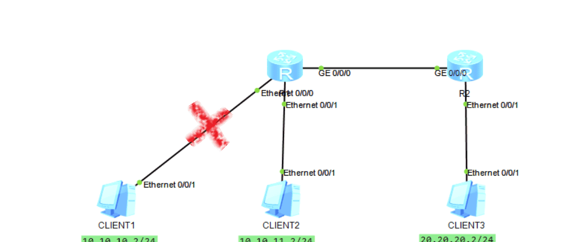
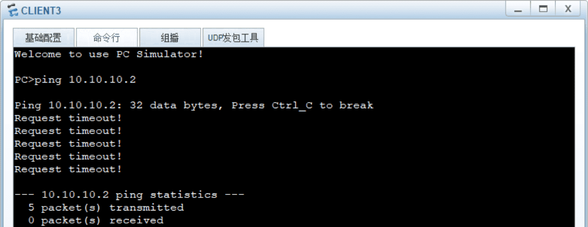
在路由器R1中,仅引入PC2的路由,不引入PC1的路由。
R2将只能学习到PC的路由,不能学习到PC1的路由
#
ip ip-prefix prefix_guolv index 10 permit 10.10.11.0 24  -- 仅学习PC2的地址段
#
route-policy LuYouGuoLv permit node 10
 if-match ip-prefix prefix_guolv

#
ospf 100 router-id 1.1.1.1
 import-route direct type 1 route-policy LuYouGuoLv  -- 引入直连路由,匹配 LuYouGuoLv
 area 0.0.0.0
  network 192.168.10.0 0.0.0.3
2.此时R2查看路由
#
<R2>disp ip routing-table
Route Flags: R - relay, D - download to fib
------------------------------------------------------------------------------
Routing Tables: Public
         Destinations : 8        Routes : 8

Destination/Mask    Proto   Pre  Cost      Flags NextHop         Interface

        2.2.2.2/32  Direct  0    0           D   127.0.0.1       LoopBack0
     10.10.11.0/24  O_ASE   150  2           D   192.168.10.1    GigabitEthernet0/0/0  -- 有PC2的地址段,但没有PC1的地址段
     20.20.20.0/24  Direct  0    0           D   20.20.20.1      Ethernet0/0/1
     20.20.20.1/32  Direct  0    0           D   127.0.0.1       Ethernet0/0/1
      127.0.0.0/8   Direct  0    0           D   127.0.0.1       InLoopBack0
      127.0.0.1/32  Direct  0    0           D   127.0.0.1       InLoopBack0
   192.168.10.0/30  Direct  0    0           D   192.168.10.2    GigabitEthernet0/0/0
   192.168.10.2/32  Direct  0    0           D   127.0.0.1       GigabitEthernet0/0/0
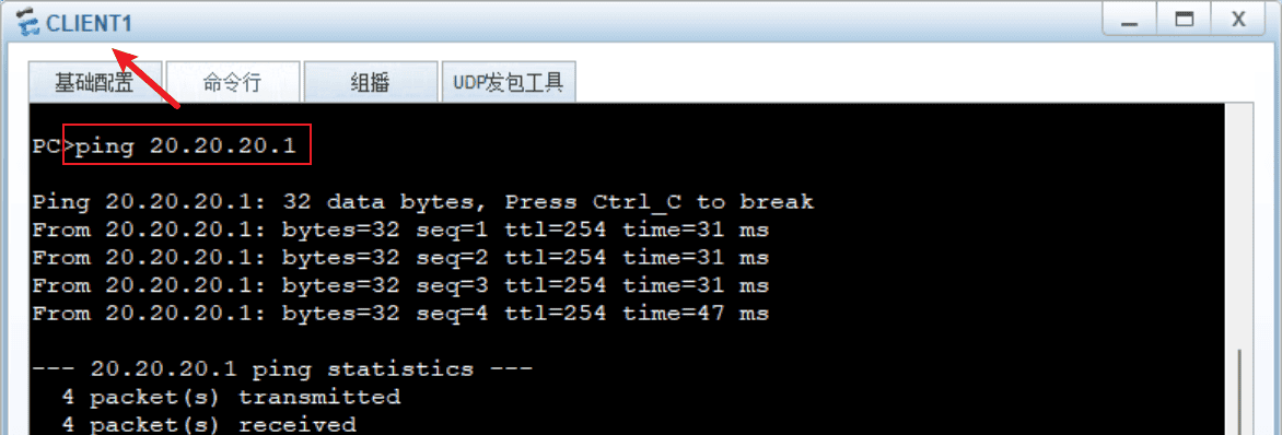
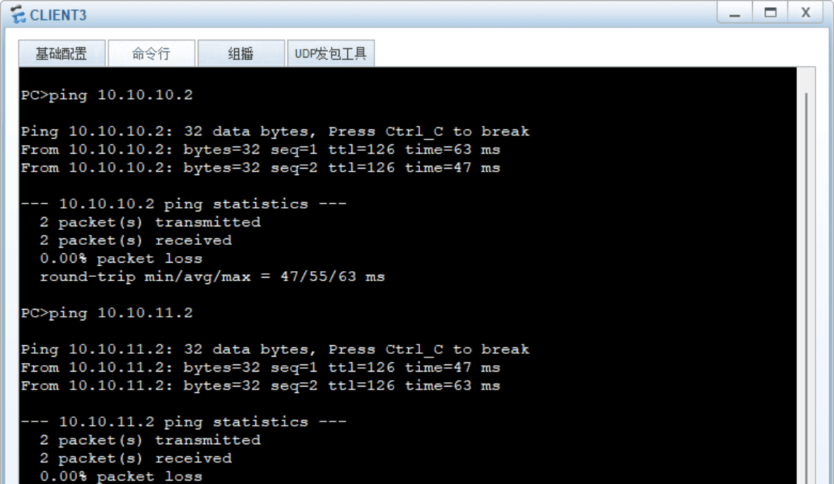
3.从PC3 PING测试验证
四、路由聚合
OSPF路由聚合是一项关键的优化技术,它能有效简化网络结构、提升稳定性和性能。
减小路由表规模,提升收敛和查找速度,抑制路由振荡,减少不必要的LSA泛洪,优化网络结构,实现逻辑分层和简化管理。
1.在R1侧对引入的直连路由(外部路由)进行聚合
详情,可以见 第二章 【OSPF区域的划分、ABR、路由聚合、LSDB】的说明。
#
<R1>disp curr conf ospf
#
ospf 100 router-id 1.1.1.1
 asbr-summary 10.10.10.0 255.255.254.0  -- 对下挂的两个/24的地址段聚合为/23的地址段
 import-route direct
 area 0.0.0.0
  network 192.168.10.0 0.0.0.3
2.此时R2查看路由
<R2>disp ip routing-table
Route Flags: R - relay, D - download to fib
------------------------------------------------------------------------------
Routing Tables: Public
         Destinations : 9        Routes : 9

Destination/Mask    Proto   Pre  Cost      Flags NextHop         Interface

        1.1.1.1/32  O_ASE   150  1           D   192.168.10.1    GigabitEthernet0/0/0
        2.2.2.2/32  Direct  0    0           D   127.0.0.1       LoopBack0
     10.10.10.0/23  O_ASE   150  2           D   192.168.10.1    GigabitEthernet0/0/0
     20.20.20.0/24  Direct  0    0           D   20.20.20.1      Ethernet0/0/1
     20.20.20.1/32  Direct  0    0           D   127.0.0.1       Ethernet0/0/1  -- 没有/24的地址段路由,聚合为/23的地址段
      127.0.0.0/8   Direct  0    0           D   127.0.0.1       InLoopBack0
      127.0.0.1/32  Direct  0    0           D   127.0.0.1       InLoopBack0
   192.168.10.0/30  Direct  0    0           D   192.168.10.2    GigabitEthernet0/0/0
   192.168.10.2/32  Direct  0    0           D   127.0.0.1       GigabitEthernet0/0/0
3.从PC3 PING测试验证
PC3到PC1和PC2,PING测试正常
总结
以上便是搭配ENSP模拟器对OSPF的几种常见应用场景的模拟和介绍,后续我会更新更多的实操案例和讲解,希望对您有用,更多关于数通设备的资料,持续更新中,欢迎您的关注!
如果觉得这些经验对你有用,不妨动动手指
点赞
收藏
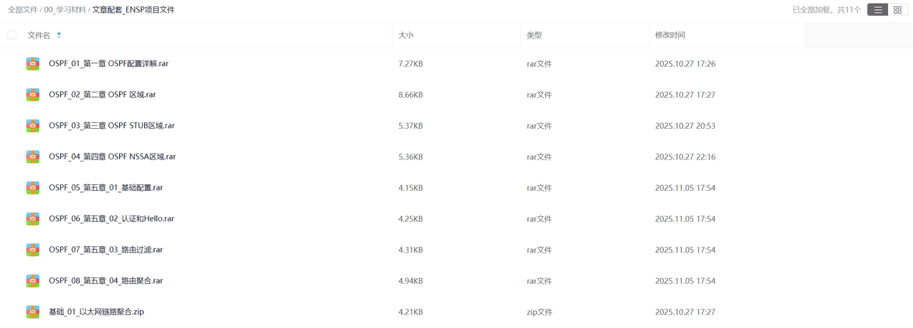
资料获取
如果您需要本期的ENSP模拟器数据,可以关注该
微信公众号
数通工程师
ENSP文件
如果您有使用问题,也可以私信我,感谢!!!


暂无评论内容